+86 13816508465
Pump Knowledge
May. 26, 2026
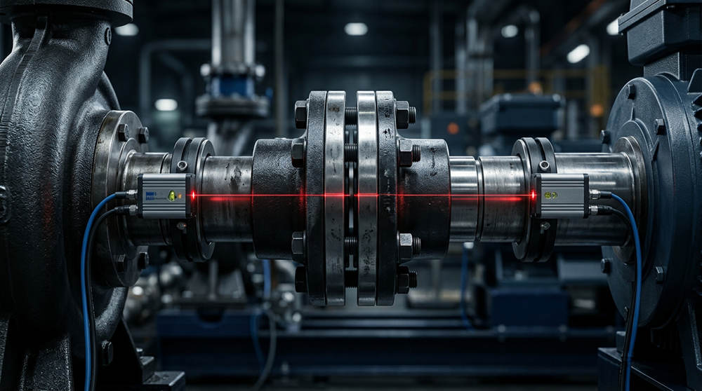
Premature pump bearing and mechanical seal failures are rarely caused by defective parts. The primary culprit is poor shaft alignment. To stop destroying new components, technicians must eliminate soft foot chassis distortion, account for thermal growth, and use precision laser alignment to correct angular and parallel deviations.
You pull a centrifugal pump offline, rebuild it with premium bearings, and install a top-tier mechanical seal. Three months later, the pump is back in the shop leaking process fluid and vibrating violently. The immediate reaction is often to blame the bearing manufacturer or assume the mechanical seal was defective out of the box. However, the root cause is almost never a manufacturing defect. The actual culprit is usually poor shaft alignment and inadequate baseplate preparation.
When rotating equipment operates at industrial speeds, such as 1450 or 2900 RPM, even microscopic deviations between the motor and pump shafts create devastating mechanical forces. A misalignment of just a few thousandths of an inch acts like a pry bar spinning thousands of times per minute inside the equipment casing. This excessive radial stress systematically destroys the microscopic fluid film inside mechanical seals, leading to severe dry running, friction, and catastrophic failure. Simultaneously, the unintended heavy load transfers directly to the rolling elements of the bearings, causing rapid fatigue, spalling, and ultimate collapse of the metal races.
If you are tired of premature mechanical failures, it is time to look at the foundation and the alignment. Precision alignment is a mandatory requirement for industrial reliability. Read on to understand the mechanics of misalignment and how to permanently correct it. (For a deeper dive into specific hardware failure modes, refer to our [Mechanical Seal Failure Analysis Guide] and [Bearing Diagnostic Guide]).
What is the difference between parallel and angular pump misalignment?
Before technicians can correct a mechanical issue, they must accurately identify it. Shaft misalignment generally falls into two primary categories, though industrial pumps almost always suffer from a compound combination of both.
Parallel misalignment, also known as offset misalignment, occurs when the centerlines of the pump shaft and the motor shaft are perfectly parallel to each other but do not meet concentrically. One shaft centerline is positioned either higher, lower, or further to the left or right than the opposing shaft centerline. Even though the shafts run in the same direction, the offset forces the coupling to constantly flex, transmitting severe radial loads directly into the pump housing and bearings.
Angular misalignment occurs when the centerlines of the pump and motor shafts intersect at an angle rather than running parallel. You can visualize this by imagining two shafts that meet at the coupling, but one is tilted slightly upward or sideways compared to the other. This creates a severe bending moment at the coupling hub. As the equipment rotates, this angular defect constantly pushes and pulls on the mechanical seal faces, destroying the precision flatness required to keep process fluid safely contained.
In the field, veteran reliability engineers rarely encounter pure parallel or pure angular misalignment. Pumps consistently display compound misalignment, meaning the motor is both offset and angled relative to the pump shaft. Modern laser alignment systems are designed to calculate this exact compound geometry, allowing technicians to make simultaneous horizontal and vertical corrections.
How do you diagnose and eliminate soft foot in industrial pumps?
You can never achieve accurate laser alignment if the machine chassis is warped. This brings us to a critical condition known as [soft foot.] Soft foot is a mechanical condition where all four mounting feet of the motor or the pump do not sit perfectly flat and flush on the baseplate.
To understand why soft foot is fatal to pump reliability, consider a standard four-legged chair sitting on an uneven floor. One leg hovers slightly above the ground. If you force that floating leg down and bolt it securely to the floor, the entire frame of the chair will twist under the stress. The exact same physics apply to an industrial motor. If you tighten the hold-down bolts on a soft foot, the cast-iron motor frame twists and distorts. This internal distortion misaligns the internal stator and rotor, creates uneven magnetic fields, and permanently bows the motor shaft. Attempting to laser-align a warped machine is mathematically impossible because the baseline geometry changes every time a technician touches a wrench to a bolt.
Instruct technicians to diagnose and correct soft foot before even turning the laser alignment system on. The procedure requires precision measurement tools. Technicians must use a dial indicator or the dedicated soft foot program on a laser system to measure the equipment accurately. The technician mounts the measuring device, fully tightens all four motor bolts, and then slowly loosens one bolt at a time. As the bolt loosens, the technician measures the [spring up] or vertical deflection of that specific foot.
The industry standard dictates that soft foot must be corrected until the deflection at every single mounting point is less than 0.05 mm (0.002 inches). To fix the issue, technicians slide precision-cut stainless steel shims under the offending foot to fill the microscopic gap. Never use brass, carbon steel, or homemade shims, as these materials compress, rust, or deform under the extreme weight of industrial motors. Only after the equipment sits perfectly flat without bolt tension can the actual shaft alignment process begin.
What is the standard operating procedure for laser shaft alignment?
Once the foundation is secure and the equipment is resting flat, technicians can proceed with aligning the shafts. Following a strict Standard Operating Procedure guarantees repeatable, data-driven results instead of relying on outdated guesswork.
Step 1: Rough Alignment
Technicians should never attach highly sensitive laser sensors to a machine that is visibly misaligned by a massive margin. Use a quality steel straightedge and feeler gauges first. The technician places the straightedge across the coupling hubs to ensure the motor and pump are generally facing the same direction. This rough alignment ensures that once the lasers are mounted, the beams will actually hit the target sensors without instantly reading [out of range] when the shafts are rotated.
Step 2: Correcting Soft Foot
As detailed extensively in the previous section, the technician measures and eliminates all soft foot conditions. The baseplate must be clean, free of rust, and devoid of old, bent shims.
Step 3: The Vertical Move
Precision alignment dictates that technicians always adjust the vertical alignment first. Vertical adjustments are achieved by adding or removing precision pre-cut stainless steel shims under the motor feet. If the laser system calculates that the motor is sitting 0.15 mm too low, the technician loosens the bolts, lifts the motor, and inserts exactly 0.15 mm of high-quality stainless steel shims under all four feet. By correcting the vertical plane first, the technician establishes a solid, flat elevation. If you attempt the horizontal move first, the act of lifting the motor to add shims will easily destroy all the horizontal progress you just made.
Step 4: The Horizontal Move
Once the vertical alignment is locked in and verified by the laser system, the technician addresses the horizontal plane. This adjustment utilizes the heavy-duty jacking bolts welded to the baseplate. Jacking bolts allow the technician to gently slide the heavy motor left or right in microscopic increments. The technician watches the live data feed on the laser alignment display, turning the jacking bolts until the horizontal offset and angularity fall precisely within the acceptable manufacturer tolerances. Once both the vertical and horizontal planes are green on the display, the technician applies the final torque sequence to the motor hold-down bolts and documents the completed alignment data.
How does thermal growth affect pump alignment at high temperatures?
Industrial pumps do not operate in a vacuum, and they certainly do not operate at a static room temperature. A critical factor that separates average mechanics from advanced reliability engineers is the ability to account for thermal growth.
Pumps typically move relatively cold or ambient process fluids. However, the electric motors driving those pumps generate massive amounts of electrical and friction heat. It is common for industrial motor casings to reach 60°C or higher during continuous operation. The laws of physics dictate that metals expand when heated. Because the motor gets significantly hotter than the pump, the motor chassis and shaft will expand and grow upwards.
A pump and motor aligned perfectly to a zero tolerance at room temperature (known as a cold alignment) will physically shift out of alignment when operating at full load (known as a hot alignment). The motor shaft will literally [grow] vertically, introducing severe parallel misalignment while the machine is running.
For critical, high-temperature applications like boiler feed pumps or hot oil circulation pumps, technicians must calculate the [Thermal Offset.] The engineering team determines the coefficient of thermal expansion for the specific cast iron or steel being used, measures the distance from the centerline to the base, and calculates the expected operating temperature delta. Based on this math, the technician intentionally aligns the motor slightly lower than the pump when the equipment is cold. As the motor heats up during operation, it grows perfectly into the correct centerline alignment, ensuring long bearing life and stress-free mechanical seals.
Rigid Foundations: The Prerequisite for Precision Alignment
Laser alignment is not an optional premium service reserved for massive corporate facilities; it is a mandatory prerequisite for pump reliability in any operation. Without precise alignment, bearings will spall, mechanical seals will shatter, and maintenance budgets will skyrocket due to unnecessary downtime.
Achieving and maintaining this critical alignment is physically impossible on a flimsy, corroded, or improperly engineered base. A precision laser alignment is only as good as the foundation supporting the machinery.
StreamPumps understands the vital relationship between structural rigidity and rotating equipment longevity. We strongly encourage maintenance managers and reliability engineers to contact StreamPumps to explore our advanced centrifugal pumps. StreamPumps systems are engineered with heavy-duty, reinforced cast-iron and fabricated steel baseplates that completely eliminate twisting, warping, and resonance. By upgrading to a rigid StreamPumps foundation, you ensure that once your technicians dial in that perfect laser alignment, it remains permanent for the lifespan of the equipment.
Frequently Asked Questions about Pump Alignment
How much does pump laser alignment cost?
The cost of pump laser alignment depends heavily on whether you utilize internal labor or hire external contractors. Purchasing a high-quality industrial laser alignment system requires an initial capital investment between $5,000 and $20,000. Hiring specialized external millwright contractors typically costs between $500 and $1,500 per pump, depending on the geographic location, equipment size, and severity of baseplate degradation.
How long does a full alignment and soft foot correction take?
A trained reliability technician can complete a standard laser alignment, including a thorough soft foot diagnosis and correction, in approximately two to four hours. However, if the baseplate is heavily corroded, requires machining, or suffers from severe pipe strain that must be corrected by pipefitters, the timeline can easily extend to a full working day per pump.
What are the risks of skipping soft foot correction?
Skipping soft foot correction guarantees that your laser alignment readings will be inaccurate and unrepeatable. The primary risk is extreme mechanical frame distortion, which bows the internal motor rotor, creates damaging electrical harmonics, and places permanent binding stress on the pump bearings. This oversight directly leads to catastrophic mechanical seal failure and destroyed bearings within weeks of startup.
What are the alternatives to laser alignment for centrifugal pumps?
The primary alternative to laser alignment is the traditional dial indicator method, specifically the reverse dial indicator technique. While a highly skilled machinist can achieve precise tolerances using dial indicators, the process is incredibly math-intensive, prone to reading errors, and struggles to account for bracket sag. Laser systems are overwhelmingly recommended because they automate complex geometry calculations and eliminate human mathematical errors.
Who is responsible for maintaining pump alignment tolerances?
Maintaining pump alignment tolerances is a shared responsibility among the mechanical maintenance team, reliability engineers, and millwrights. Reliability engineers are responsible for establishing the acceptable tolerance specifications and calculating thermal growth targets. Field millwrights and industrial pump technicians are responsible for executing the physical alignment, correcting baseplate defects, and meticulously documenting the final alignment data.
Address
No.17 XeDa Jimei Ind. Park, Xiqing Economic Development Area, Tianjin, China
Telephone
+86 13816508465
QUICK LINKS