+86 13816508465
Pump Knowledge
May. 27, 2026
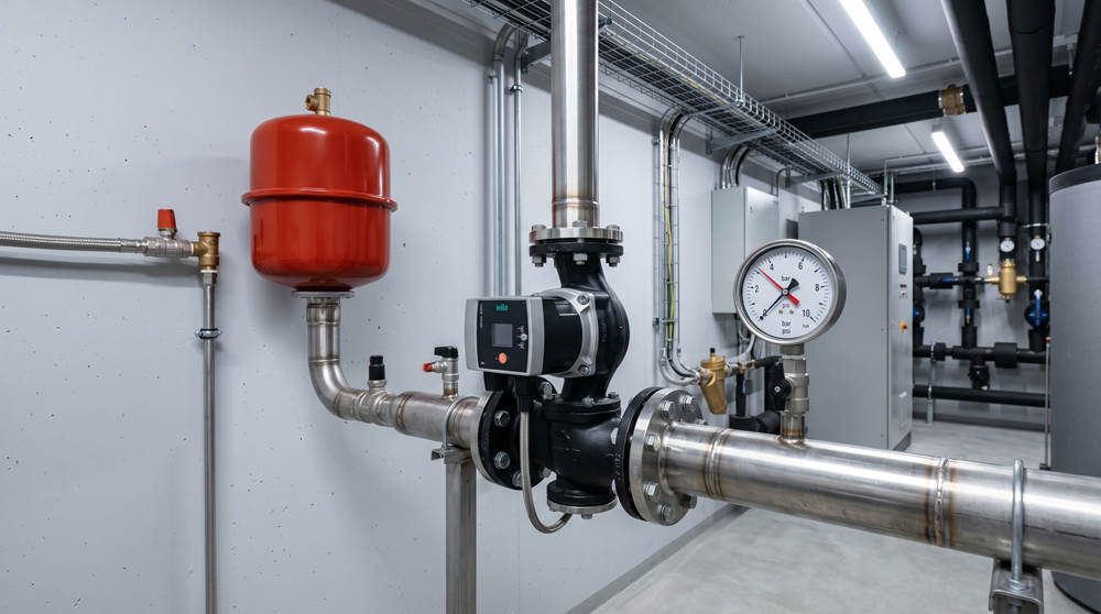
Circulation pump failure is frequently misdiagnosed; the root cause is often low system static pressure leading to cavitation. To prevent recurrent pump damage, engineers must diagnose and resolve expansion vessel failures and adhere to the [pumping away] installation principle before replacing the circulation pump.
Mechanical noise in a closed hydronic system is a critical diagnostic indicator. Frequently, maintenance personnel report severe mechanical noise—often described as a grinding acoustic signature—emanating from the circulation pump. The standard, yet flawed, field response is the immediate replacement of the pump unit. However, facility managers and mechanical, electrical, and plumbing (MEP) engineers often observe that the replacement pump develops the exact same mechanical fault shortly after commissioning.
This recurrent failure indicates a fundamental diagnostic error. The circulation pump is rarely the primary defect. In the vast majority of hydronic system failures, the root cause is low system static pressure. Operating a pump under deficient static pressure creates a highly destructive physical condition within the pump volute. Understanding the underlying system dynamics is mandatory for preventing premature equipment degradation. This article provides a comprehensive technical analysis of circulation pump failure mechanisms, expansion vessel diagnostics, and system design protocols.
To diagnose recurrent pump failure, engineers must analyze the fluid dynamics occurring at the pump impeller. In a closed hydronic system, the operational fluid (water or a water-glycol mixture) does not need to reach 100°C to undergo a phase change from liquid to vapor. Vaporization is a function of both temperature and pressure.
If the system static pressure drops significantly below the required operational threshold, high-temperature fluid (for example, operating at 80°C) will vaporize instantly upon reaching the pump's suction inlet, where localized pressure is at its lowest. This phase change generates microscopic vapor bubbles within the fluid stream.
As these vapor bubbles travel through the pump volute, they move from the low-pressure suction zone into the high-pressure discharge zone created by the spinning impeller. The sudden increase in pressure causes the vapor bubbles to violently compress and collapse. This thermodynamic process is defined as cavitation.
Cavitation produces extreme localized shockwaves. These micro-implosions are the source of the severe grinding noise frequently misdiagnosed as mechanical bearing failure. Furthermore, cavitation causes rapid, irreversible material erosion on the metallic surfaces of the pump impeller and volute. Over a short operational period, this erosion destroys the pump's hydraulic efficiency, destabilizes the impeller balance, and ultimately causes complete mechanical failure.
Understanding why system pressure drops necessitates an examination of the expansion vessel. The expansion vessel is a critical safety and pressure-regulation component in any closed hydronic heating or cooling network. Its primary function is to absorb the volumetric thermal expansion of the system fluid as it heats, thereby maintaining a stable system static pressure (typically designed around 1.5 bar for standard commercial applications).
The internal architecture of a standard expansion vessel consists of a steel tank divided by a flexible rubber diaphragm. One side connects to the hydronic system and fills with fluid; the other side contains a compressible gas (usually nitrogen or air) pre-charged to a specific pressure.
If the expansion vessel loses its pre-charge gas pressure due to a microscopic valve leak, or if the internal rubber diaphragm ruptures due to material fatigue, the vessel can no longer absorb fluid expansion. Consequently, the hydronic system becomes hydraulically locked.
Without a functional expansion zone, the system experiences extreme pressure fluctuations. When the boiler ignites and the fluid temperature rises, the fluid expands, causing an immediate pressure spike. This high-pressure state forces the system safety relief valve to open and discharge system fluid to prevent structural pipe rupture.
Conversely, when the heating cycle ends and the fluid cools, the fluid volume contracts. Because the safety relief valve previously discharged fluid, the system now lacks sufficient total volume. The system pressure subsequently drops to near-zero levels. Operating a circulation pump under these severely depleted static pressure conditions inevitably induces the vaporization and cavitation cycles detailed in the previous section.
Before authorizing the replacement of a cavitating circulation pump, technicians must verify the operational integrity of the expansion vessel. MEP engineers should enforce strict diagnostic protocols during system maintenance. The following tests provide immediate verification of vessel status.
The acoustic test is a preliminary, non-invasive diagnostic procedure. Instruct technicians to gently strike the upper and lower sections of the expansion vessel casing with a metallic tool.
In a functional vessel, the section containing the pre-charged gas will emit a distinct, resonant hollow sound. The section connected to the system fluid will emit a dense, solid sound. If both the upper and lower sections emit a solid, dense acoustic signature, the internal diaphragm has ruptured, and the entire vessel is flooded with system fluid. The vessel requires immediate replacement.
The Schrader valve test provides absolute confirmation of the internal diaphragm's integrity. The Schrader valve is the pneumatic fitting used to apply the gas pre-charge, typically located under a protective cap on the gas chamber side of the vessel.
Instruct technicians to briefly depress the central pin of the Schrader valve.
If pressurized gas is released, the pre-charge chamber is intact, though the precise pressure must still be verified with a calibrated pneumatic pressure gauge to ensure it matches system specifications.
If hydronic system fluid is discharged from the Schrader valve, the internal rubber diaphragm has suffered a critical structural failure. The fluid has breached the gas chamber. The expansion vessel is completely defunct and must be replaced immediately prior to installing a new circulation pump.
Beyond component failure, fundamental piping architecture directly influences pump longevity. The positioning of the circulation pump relative to the expansion vessel dictates the dynamic pressure distribution throughout the entire pipe network. This relationship centers on the Point of No Pressure Change (PONPC).
The PONPC is the specific location where the expansion vessel connects to the main hydronic circuit. Regardless of whether the circulation pump is operating or idle, the system pressure at the PONPC remains constant, governed solely by the expansion vessel's internal pressure.
Historically, many systems were installed with the circulation pump located upstream of the expansion vessel, pumping fluid directly towards the PONPC. This configuration is mathematically and hydraulically detrimental.
When a pump operates, it generates a differential pressure (head). If the pump pushes fluid towards the PONPC, the pump's differential pressure is subtracted from the system's baseline static pressure. This subtraction induces negative dynamic pressure at the pump's suction inlet. Negative suction pressure actively facilitates dissolved air ingress through pipe fittings, lowers the fluid vaporization threshold, and triggers immediate cavitation.
To ensure maximum system stability, MEP engineers must enforce the [pumping away] principle. The circulation pump must be installed downstream of the expansion vessel, pumping fluid away from the PONPC.
In this configuration, the pump's differential pressure is added to the baseline system static pressure. This additive effect guarantees a positive dynamic pressure state throughout the entire hydronic network, especially at the pump's suction inlet. Maintaining high positive pressure at the suction inlet is the most effective engineering method for suppressing fluid vaporization and eliminating cavitation.
Diagnosing severe pump noise requires a disciplined, systemic approach rather than immediate component replacement. Engineers and technicians must prioritize system-level diagnostics by verifying the accuracy of the system pressure gauge and executing rigorous tests on the expansion vessel. Replacing a circulation pump without rectifying a ruptured expansion vessel or correcting a flawed upstream installation will guarantee the destruction of the replacement unit.
To further protect hydronic infrastructure, MEP engineers should specify premium circulation pumps that feature optimized internal hydraulic designs. Specifically, specifying pumps with a precisely engineered, low Net Positive Suction Head required (NPSHr) rating provides a significantly wider operational safety margin against minor system pressure fluctuations. By maintaining stable system pressure, confirming expansion vessel integrity, and adhering to the pumping away principle, facility managers can eliminate cavitation and ensure the maximum lifecycle of their hydronic pumping equipment.
The optimal static pressure depends on the vertical height of the building and the operational temperature. For standard single-story or two-story commercial facilities, the baseline static pressure is typically engineered at 1.5 bar (150 kPa). However, engineers must calculate the specific static head (0.1 bar per meter of building height) and add a safety margin of 0.3 to 0.5 bar to determine the precise pre-charge pressure for the expansion vessel.
Expansion vessels require mandatory inspection during annual preventive maintenance cycles. The static pre-charge pressure must be verified while the hydronic system is depressurized. Annual verification ensures the diaphragm remains flexible and the gas charge is sufficient to absorb thermal expansion safely.
NPSHr stands for Net Positive Suction Head required. It is a metric provided by the pump manufacturer indicating the absolute minimum fluid pressure required at the pump's suction inlet to prevent the fluid from vaporizing and causing cavitation. A lower NPSHr rating means the pump can operate safely under lower system pressure conditions.
Yes, cavitation can occur even if the overall system static pressure appears normal. This occurs if there is a severe localized flow restriction immediately upstream of the pump, such as a clogged Y-strainer or a partially closed isolation valve. The restriction creates a severe pressure drop directly at the pump inlet, plunging the local pressure below the fluid's vaporization point and inducing cavitation.
Address
No.17 XeDa Jimei Ind. Park, Xiqing Economic Development Area, Tianjin, China
Telephone
+86 13816508465
QUICK LINKS